
No. IMPERX does not ship test reports with each camera. These test reports, called Passports, can be requested from IMPERX. Passports show the factory test results and other critical information about the configuration of the camera as it is configured and tested in the factory. Passports contain the following information;
IMPERX Inc. Bobcat Camera Passport Info & Parameters
| General Information | Taps Parameters | AFE Parameters | Graphs |
|---|---|---|---|
| Evaluation Date | Tap # | Tap # | Linearity |
| Camera Name | Dark Bias | Slow Speed | Photon Transfer Curve |
| Serial Number | Dark Bias Dev | AFE CDS Gain | |
| Assembly Number | SNR (dB) | Gain | |
| Sensor S/N | TN (dB) | Offset | |
| FW_Version | SNX (dB) | Fast Speed | |
| Custom Version | SNY (dB) | AFE CDS Gain | |
| RGS Version | eGain | Gain | |
| XML Version | Read Noise | Offset | |
| MAC Address | Non Linearity | ||
| Bit Depth | |||
| Temperature | |||
| MFG Date | |||
| Pre-Amp Gain | |||
| Widthmax | |||
| Heightmax |
Topic: Camera Manufacturing Test Reports
Keywords: Test Reports, Camera Configurations, Passports
No, a customer should not consider changing Image Sensors. Cameras are configured in the factory using very specialized proprietary software applications along with special test fixtures. This configuration, unique to each camera and sensor, is stored in memory on the camera. A replacement sensor would require re-configuration in the factory. Also working on a camera requires a cleanroom environment and sound ESD measures. Any attempt to repair or modify a camera in the field voids the warranty.
Topic: Remove and replace image sensor
Keywords: Sensor, Repair, Replace
Bobcat Cameras do not contain any user accessible non-volatile memory that can be used to store images, data, or any user files.
User control interfaces provide functionality only for control of the operating parameters of the camera. Camera feature access is performed by reading or writing control sequences to internal registers within the camera. The structure of the command and response sequence is outlined in the Bobcat Camera User’s Manual.
Internal volatile memory is used only to temporarily buffer image data prior to transition. Image data is not stored or buffered in any non-volatile memory. All volatile memory is lost upon loss of external power. The camera does not contain batteries or alternate sources of power.
Topic: Non-volatile memory for cameras
Key-Words: Memory, Volatility, Architecture, Security
All IMPERX standard model cameras are built using Grade 1 Image Sensors. Custom Cameras may use other grade sensors depending on the desire of the customer.
Topic: Sensor Grade
Key Words: Image Sensors, Grade, Class
Image Sensors are graded based on the number of pixel (dark field defective bright and bright field defective dark), cluster, and column defects. These numbers vary based on sensor part number (size). One must review the specifications for the sensor in question.
Topic: Sensor Grade
Key Words; Image Sensors, Grade, Class
In addition to the size of the sensor, the manufacturer of the sensor, and the number of taps, customers have a number of options of lens mount adapters, type of color, and optical filters.
Topic: Camera Options
Key-Words: Options, Color, Lens Mount, Filters
Yes. All Imperx Cameras Control Software released after 2014 supports Windows 10.
Topic: Software compatibility with Windows 10
Keywords: Control Software, Windows 10
If you cannot see the Imperx CameraLink camera in the list of available ports, then the associated .dll file that came with your frame grabber is not in the correct location. The Bobcat CameraLink configurator GUI is looking in the C:\Windows\System32\ folder for the clsrxxx.dll (where “x” would indicate the specific manufacturer Camera Link Serial .dll that came with your frame grabber.) If the file is not in the \System32 folder, please copy the file into this folder and re-open the CameraLink Configurator.
Applicable Products: Cameras (CameraLink)
Topic: CameraLink serial dll location
Keywords: CameraLink, FrameGrabber
A CCD imager is composed of a two-dimensional array of light sensitive pixels. In general, the majority of the pixels have similar sensitivity. Unfortunately, there are some pixels which sensitivity deviates from the average pixel sensitivity. A defective pixel is defined as a pixel whose response deviates by more than 15% from the average response. In extreme cases these pixels can be stuck ‘black’ or stuck ‘white’ and are non-responsive to light. There are two major types of pixel defects – “Defective” and “Hot”.
- ”Defective” – these are pixels which sensitivity deviates more than 15% due to fluctuations in the CCD manufacturing process. Two type of defective pixels are possible:
- “DARK” is defined as a pixel, whose sensitivity is lower than the sensitivity of the adjacent pixels. In some cases, this pixel will have no response (completely dark).
- “BRIGHT” is defined as a pixel, whose sensitivity is higher than the sensitivity of the adjacent pixels. In some cases, this pixel will have full response (completely bright).
- “Hot” – these are pixel, which in normal camera operation behaves as normal pixel (the sensitivity is equal to the one of the adjacent pixels), but during long time integration behaves as a high intensity bright pixel. In some cases, this pixel will have full response (completely bright).
2.16.1 Static Pixel Correction
Static Defective and Hot pixel correction works with predetermined and preloaded Defective and Hot pixel maps. During factory final testing, our manufacturing engineers run a program specially designed to identify these ‘defective’ and “hot” pixels. The program creates a map file which lists the coordinates (i.e. row and column) of every defective pixel. This file, called the Defect Pixel Map, is then downloaded into the camera’s non-volatile memory.
Users may wish, however, to create and to upload their own DPM file because of the uniqueness of their operating environment or camera use.
When ‘Defective Pixel Correction’ is enabled, the camera will compare each pixel’s coordinates with entries in the ‘defect’ map. If a match is found, then the camera will ‘correct’ the defective pixel. When ‘Hot Pixel Correction’ is enabled, the camera will compare each pixel’s coordinates with entries in the ‘defect’ map. If a match is found, then the camera will ‘correct’ the hot pixel. The "Defective/Hot Pixel Map" can be displayed upon user request.
2.16.1 Dynamic Pixel Correction
Dynamic pixel correction works without preloaded pixel maps. When this option is enabled, the camera determines which pixel needs correction and performs the correction automatically. Static and Dynamic “Defective Pixel Correction” and “Hot Pixel Correction” can be enabled independently or simultaneously.
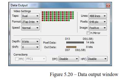
In order to enable or disable defective pixel correction, open the Data Output menu from your Bobcat GUI. Select which type of pixel correction you’d like to enable by using the drop-down menus to the lower right of the menu, seen above.
Corrections:
DPC – enables Defective Pixel Correction (DPC). Each camera comes with a built-in Defective Pixel Map (DPM) to correct for defective pixels. The user can upload a custom DPM.
HPC – enables Hot Pixel Correction (HPC). Each camera comes with a built-in Hot Pixel Map (HPM) to correct for hot pixels. The user can upload a custom HPM
Topic: Defective/Hot Pixel Data Correction
Keywords: Hot pixel correction, defective pixel correction, hot pixel map, defective pixel map, HPC, DPC, HPM, DPM
<!–*OBTAINING INFORMATION FOR CHEETAH SPECIFIC “Fixed pattern noise” –>
The camera exposure can be controlled using an external pulse, supplied to the camera. The pulse duration determines the exposure. For stable operation, this pulse MUST be synchronized with the camera frame timing. Please refer to “I/O Control” section for pulse mapping information.
Applicable Products: Bobcat cameras
Topic: External Exposure Control
Keywords: External, Exposure Control
A CCD imager is composed of a two dimensional array of light sensitive pixels. Each pixel within the array, however, has its own unique light sensitivity characteristics. Most of the deviation is due to the difference in the angle of incidence and to charge transport artifacts. This artifact is called ‘Shading’ and in normal camera operation should be removed. The process by which a CCD camera is calibrated for shading is known as ‘Flat Field Correction ‘This feature is available as a standard feature only for cameras with 1.0” optical format or bigger.
The BOBCAT series of cameras incorporate a Flat Field Correction mechanism. The Flat Field Correction mechanism measures the response of each pixel in the CCD array to illumination and is used to correct for any variation in illumination over the field of the array. The optical system most likely introduces some variation in the illumination pattern over the field of the array. The flat field correction process compensates for uneven illumination, if that illumination is a stable characteristic of each object exposure.
During factory final testing, our manufacturing engineers run a program specially designed to identify the shading characteristics of the camera. The program creates a Flat Field Correction file, which contains coefficients describing these shading characteristics. This file is then downloaded into the camera’s non-volatile memory. When Flat Field Correction is enabled, the camera will use the Flat Field Correction coefficients to compensate for the shading effect.
Each IMPERX camera is shipped with the Flat Field Correction file that was created for that camera during factory final testing. Users may wish, however, to create their own Flat Field Correction file because of the uniqueness of their operating environment (i.e. lens, F-stop, lighting, etc.). Therefore, IMPERX provides a Flat Field Correction utility that allows users to generate a Flat Field Correction file. This file can then be downloaded into the camera. While creating the Flat Field Correction file, it is necessary to illuminate the CCD with a light pattern that is as representative of the background illumination as possible. This illumination should be bright enough, or the exposure made long enough, so that the CCD pixels signals are at least 25 percent of full scale (for 12-bit mode the level should be at least 1000 ADUs).
Applicable Products: Bobcat cameras
Topic: Flat Field Correction
Keywords: FFC, Flat Field Correction; Shading,
The camera speed (frame rate) depends on the CCD “read-out” time – the time necessary to read all the pixels out of the CCD imager. The frame rate can be calculated using the following Formula 1.1:
Frame rate [fps] = 1 / read-out time [sec] (1.1)
The user can program the camera to run slower than the nominal speed preserving the camera full resolution. The user can independently extend the camera line time (the time required to read one line out of the CCD imager) and camera frame time (the time required to read the entire frame out of the CCD imager). The camera line time can be extended to ~ 200 us, with a precision ~ 25 ns. The camera frame time can be extended to ~ 16 sec, with a precision of ~ 1.0us.
Applicable Products: Bobcat cameras
Topic: Camera Speed (Frame Rate)
Keywords: Speed, Frame Rate, Read-Out Time
The camera can be set to automatic gain (and exposure) control in order to keep the same image brightness during changing light conditions.
In this mode the user sets the image brightness (luminance) to be maintained, and the camera adjusts the gain accordingly. The user can also select the average or peak brightness to be maintained.
The camera starts with changing the gain within the preset by the user min-max limits. If one of the gain limits has been reached, the camera indicates the limit has been reached and keeps the value until the light condition change. The speed of convergence (how fast the camera stabilizes after change), can be preset by the user (four possible options are available).
If both modes, automatic exposure and automatic gain are enabled simultaneously, the camera starts with changing the exposure first within the preset by the user min-max limits. If one of the exposure limits has been reached, the camera engages the analog gain, and changes it within the preset by the user min-max limits.
The AGC algorithm samples all pixels for the entire frame, but the user can select only a portion of the image (AOI) to be used as a sample collecting region. The camera displays the current luminance, current exposure and current gain.
For auto exposure control refer to Automatic Exposure Control (AEC) section.
Applicable Products: All cameras
Topic: Analog gain control
Keywords: Automatic gain control, AGC
On Semiconductor, a supplier of CCD image sensors to Imperx, is adopting a new Color Filter Array (CFA) materials for all its color interline CCD image sensors. This new CFA materials (Gen 2 CFA materials) provides reduced color crosstalk and better color fidelity with only minor changes to the spectral characteristics as shown in the curves below.
Customers may find that adjustments to the color correction matrix coefficients (from those used with current Imperx camera) is required for best color performance. An application note from On Semiconductor is attached and provides an example of how the color correction matrix coefficients can be adjusted, if desired.
Applicable Products: Bobcat cameras
Topic: Gen2 Color Sensors
Keywords: Generation 2, Gen2, Color, Truesense, Bayer, Filter Material, CFA
Vertical Binning is done in the time domain, where the data from the binned lines is added in the CCD. The vertical binning is performed first, and the vertical AOI is second. The vertical AOI settings are referenced to the binned image. If the user wants to set a vertical window of 200 lines, the user has to put 200 in the AOI height register regardless of the selected vertical binning mode.
Horizontal Binning is done in the digital domain, where the data from the binned pixels is added digitally. The horizontal binning is performed first, and the horizontal AOI is second. The horizontal AOI settings are referenced to the binned image if the user wants to set a horizontal window in the binned image with width 200 the user has to put 200 in the AOI width register regardless of off the selected horizontal binning mode.
Applicable Products: Bobcat cameras
Topic: Vertical versus Horizontal Binning
Keyword: Vertical, Horizontal, Binning
The image resolution is determined by the number of pixels per line and number of lines per frame. The image is framed by two signals LVAL, enveloping the valid pixels in a line, and FVAL – enveloping the valid lines in a frame. The camera offers two independently selectable LVAL and FVAL sizes. The first LVAL value envelops all visible pixels in a line (active pixels plus buffer pixels) and the second – only the active pixels. Respectively, the first FVAL envelops all visible lines in a frame (active lines and buffer lines), and the second – only the active lines. The camera speed (Frames per Second) is the same for both image size selections. Typically, the pixels outside of LVAL and FVAL (primarily dark pixels and lines) are masked with zeros, but in BOBCAT, the user has an option to mask or not to mask these pixels or lines.
Applicable Products: Bobcat cameras
Topic: Image Resolution
Keywords: Image Resolution, Speed, Frames per Second
700 nm.
Applicable Products: All color cameras
Topic: IR Cut Filters
Keywords: IR, Filters, Cut, Wavelength
The camera has a built in Lens Controller that outputs Zoom, Focus, and Iris control signals for a standard Type 1 (6V) or Type (12V) C-Mount motorized lens. Output Lens Control signals are controlled via the Bobcat CamConfig GUI, or command terminal.
Note: ICL, and IGV cameras do not support Lens Control. Only CLB, CLM, and GEV cameras support Lens Control.
Applicable Products: Bobcat Gen2 cameras
Topic: Focus, Zoom and Iris Lens Control
Keywords: Lens Control, Controller, Zoom
All cameras from Imperx with that include sensors 1” or smaller do include video iris lens control option. This feature is included with all cameras and the control comes through the male 12-pin Hirose in the rear of the camera. If you wish to utilize our power supply, we offer the PS12V05 which includes the auto-iris standard 4-pin connection.
Note: Auto-Exposure and Auto-Gain conflicts with the use of the auto-iris. Therefore, select AEC/AGC or Auto-Iris, not both.
Applicable Products: Bobcat cameras
Topic: Auto Iris Lens Control
Keywords: Lens Control, Controller, Zoom,
No, not generally. Occasionally IMPERX will sell lenses or requested optics along with cameras per special request by customers.
Applicable Products: All cameras
Topic: Lenses, Optics
Keywords: Lenses, Filters, Optics
If the camera is only showing half of the image with the other half being black, switch the Tap format to single to see if the image clears up. It the image clears up or not, then either way there is a tap failure in the CCD Sensor. An RMA is required to fix the camera. Please contact [email protected] or your local distributor to initiate an RMA process.
Applicable Products: Cameras
Topic: No Image or Half Image from camera
Keywords: Output Image, Test Image
You can only control the exposure timing for the first image. It is a variable time depending on the camera model that you have. Please see chart below for minimum exposure timing for the first frame. The second frame will always be a full frame exposure based on the standard readout time for the camera (FTM).
Minimum Exposure Times:
- B0610, B0620, B1020, B1320, B1621, B1921, B1922, B2320 and B3320 2us.
- B1410, B1610 and B4821 4us
- B2510, B2520 and B6620 8us
- B1620, B1920, B2020, B4020 and B4820 and 10us
Applicable Products: Bobcat cameras
Topic: PIV exposure control for Bobcat cameras
Keywords: PIV Triggering, Exposure Control
Yes, IMPERX cameras are made using Industrial grade components. The temperature, shock, and vibration specs are some of the toughest in the industry. Aerospace companies have tested IMPERX cameras to even harsher conditions and use them in launch and near space scenarios. IMPERX has also developed an enclosure for aircraft applications which has been tested to DO-160.
Applicable Products: Bobcat cameras
Topic: Environmental
Keywords: Harsh Environment, Rugged, Specs, Industrial, Aviation, DO-160
Operational settings for the camera may be stored for later retrieval in its non-volatile memory. Three separate configuration spaces exist for storing these settings: ‘factory’ space, ‘user #1’ space and ‘user #2’ space.
The factory space is pre-programmed by factory personnel during the manufacturing process. This space is write protected and cannot be altered by the user. Two user spaces are also provided allowing the user to store his/her own preferences.
The camera can be commanded to load its internal workspace, from either of the three configuration spaces, at any time. The user can also define from which space the camera should automatically load itself following a power cycle or receipt of a reset ( ‘SW_Reset’) command.
Loading saved settings can be done either by register or by command.
Using the Boot From Register
This register determines which configuration space (factory, user#1 or user #2) should be loaded into the camera following a power cycle or reset ( ‘SW_Reset’) command.
Upon a power cycle or reset, the camera reads the ‘boot from’ value from non-volatile memory and loads the appropriate configuration space.
Address : 0x6000
Data (1- 0):
- – Boot from Factory
- – Boot from User #1
10 – Boot from User #2
Data (31- 2) : N/A
The ‘SW_Reset’ Command
The ‘SW_Reset’ command instructs the camera to initiate software reset, which resets the camera and loads its workspace from one of the configuration spaces as determined by the ‘Boot From’ data. Although, this is a command, the user MUST write a specific data 0xDEADBEEF in order to initiate the reset sequence.
Address : 0x601C
Applicable Products: Bobcat and Cheetah cameras
Topic: Camera
Keywords: Camera Settings, User Space, Factory Space, Boot From, Load From
Yes. IMPERX, through its’ supply change is participating in Sony’s last-time-buy program to secure and continuing supply of CCD sensors throughout the term of the Applicable Productions phase-out period. This is bases on past sales history of these sensors and forecasts from customers.
Applicable Products: Bobcat cameras
Topic: Sony CCDs
Keywords: Sony, CCD Sensors, Discontinuation, Sony Sensors
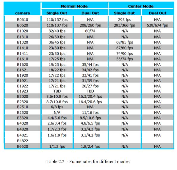
BOBCAT camera series provides a unique way to control and increase the camera nominal (free-running) speed. The user can select (normal) or (over-clock) camera speed. The “Slow” speed is the camera nominal frame rate as determined by the CCD manufacturer. Since BOBCAT internal design is optimized for higher clock rates, it is possible to over-clock the camera (use an internal clock higher than the recommended one), which will result in higher (~ 20%) frame rate. Special measures have been taken in order to preserve the camera performance when over-clock mode is used. The possible frame rates are shown in Table 2.2, where the camera speed is the shown in [FPS)]. The first number represents the “normal” speed, and the second – “over-clock” speed.
Applicable Products: Bobcat cameras
Topic: Camera clock speed
Keywords: Camera Speed, Normal Clock, Overclock
The camera has a dual red-green LED, located on the back panel. The LED color and light pattern indicate the camera status and mode of operation:
- GREEN is steady ON – Normal operation. The user is expected to see a normal image coming out of the camera.
- GREEN blinks with frequency ~ 0.5 Hz – indicates triggering mode.
- GREEN blinks with frequency ~ 2.0 Hz – indicates programmable integration (line, frame or both) mode.
- YELLOW is steady ON – Test mode. The user is expected to see one of the test patterns.
- YELLOW blinks with frequency ~ 0.5 Hz – the camera is in AGC/AEC mode. In this mode changing the shutter slider will not affect the image luminance.
- YELLOW blinks with frequency ~ 2.0 Hz – the camera is in external H or V sync mode. The camera timing will be slaved to the external pulses. Changing programmable integration sliders will not affect the image luminance
- RED is steady ON – RS232 communication error or firmware load error. Re-power the camera and load the factory settings. If the condition is still present, please contact the factory for RMA.
- LED is OFF – Power not present error. The camera has no power or indicates a camera power supply failure. A faulty external AC adapter could also cause this. To restore the camera operation, re-power the camera and load the factory settings. If the LED is still “OFF”, please contact the factory for RMA.
Applicable Products: Bobcat cameras
Topic: Status LED
Keywords: LED, Status, Green, Yellow, Red, Blinks
The strobe output is used to synchronize an external light source with the camera timing, and thus to maximize the camera efficiency in low light level conditions. The optimal strobe signal position is achieved by the positioning of the STROBE pulse, with respect to the vertical transfer pulse VCCD (end of the frame) - Figure 2.19. BOBCAT supports two independent strobe signals. Each strobe pulse can be positioned within the entire frame timing period with a precision 1.0 us. The strobe duration can be seen from 1.0 us to 65535 us with a precision of 1.0us. The internal camera timing has a flag for odd and even frames. Each strobe can be assigned to every frame, only odd frames, only even frames, or the strobe can be disabled. The actual strobe signal can be mapped to the corresponding camera outputs.
Applicable Products: Bobcat cameras
Topic: Strobe Output
Keywords: Strobe Output, Synchronize
The user has the capabilities to superimpose over a live image the following test patterns. The user can change the brightness of the superimposed image from black (invisible) to white. Image superimposition is not available during H & V binning.
- “Crosshair” – Crosshair watermark (2 pixels and 2 lines thickness) indicating the absolute image center of the image.
- “H & V Lines” – A pair of Horizontal and Vertical lines can be positioned in the image. The user can enable the lines in horizontal, vertical or both directions, and to position them at any pixel/line in the image. Since the H & V lines can be used as a measuring tool, the pixel and line positions are referenced to the CCD pixels and lines, not to the image pixels and lines. The spacing between the lines can be displayed in: 1. Pixels - Natively, the spacing between the lines is shown in pixels
- Metrical units - In addition, the user can use these lines as a measuring tool. The user can apply a scale coefficient and thus, to calculate the spacing in linear measuring units (micrometers, millimeters or meters).
Applicable Products: Bobcat cameras
Topic: Super Imposition
Keywords: Super Impose, Metrical Units, H & V, Horizontal, Vertical, Crosshair
The camera has a built in temperature sensor which monitors the internal camera temperature. The sensor is placed on the hottest spot in the camera. The internal camera temperature is displayed on the Camera Configuration Utility screen and can be queried by the user at any time – refer to Camera Configuration section.
Applicable Products: All cameras
Topic: Temperature Sensor
Keywords: Temperature, Sensor, Monitor
The camera can output several test images, which can be used to verify the camera’s general performance and connectivity to the frame grabber. This ensures that all the major modules in the hardware are working properly and that the connection between the frame grabber and the camera is synchronized – i.e., the image framing, output mode, communication rate, etc. are properly configured. Please note that the test image patterns do not exercise and verify the CCD’s functionality.
The following test images are available:
- - Black – displays black image (value x0000)
- - Gray – displays a uniform dark gray image (value x2000)
- - White – displays a uniform white image (value 3FFF)
- - H Ramp Still – displays a stationary horizontal ramp image
- - V Ramp Still – displays a stationary vertical ramp image
- - H Ramp Move – displays a moving horizontal ramp image
- - V Ramp Move – displays a moving vertical ramp image
- - Vertical Bars – displays a set of 8 vertical gray bars with different gray levels.
Applicable Products: Bobcat cameras
Topic: Test Image Patterns
Keyword: Test Images, Patterns
In the normal mode of operation, the camera is free running. Using the trigger mode allows the camera to be synchronized to an external timing pulse. There are three input modes available for external triggering – software (CC), internal (pulse generator), and external. Please note that the desired trigger input has to be mapped to corresponding camera input. For more information, please refer to the I/O Control section.
- - “External” – the camera receives the trigger signal coming from the connector located on the back of the camera.
- - “Computer” – the camera receives the trigger signal command from the frame-grabber.
- - “Internal” – the camera has a built in programmable pulse generator – refer to “Pulse Generator” section. In Internal triggering mode the camera receives the trigger signal from the internal pulse generator.
- - “Software” – the camera receives the trigger signal which is computer generated. The camera expects a one clock cycles pulse generated by the computer. The trigger exposure is internal register controlled. Pulse duration exposure is not allowed
Applicable Products: Bobcat cameras
Topic: Trigger Input Modes
Keywords: Trigger, External, Computer, Internal, Software
A new innovation to the Bayer (RGB Red, Green, Blue) pattern is the TRUESENSE (Sparse) color filter pattern. The TRUESENSE Color Filter pattern uses a technology which provides a 2x improvement in light sensitivity as compared to a standard color Bayer pattern. This technology utilizes panchromatic filters (filters that are sensitive to all colors of light) in addition to the standard green, red, blue filters.
Applicable Products: Bobcat cameras
Topic: Truesense vs Bayer Color Rev 2
Keywords: Color Pattern, Truesense Color, Bayer Color, Light Sensitivity, Sparse CFA, RGB
Yes, there is a new tool that has been packaged with the newer versions of the GEV, HD-SDI, CoaXPress and CameraLink cameras. The tool is called the Bobcat Upload Manager. To use this tool, you will need to ensure:
-That the camera is connected to the computer,
-That power is applied to the camera, and
-That is not being connected to through any other application (GEV Player, or Bobcat CL Configurator or HD-SDI Configurator).
With regards to update the cameras FW, you should have received a .zip folder from the support team that will have the .RPD and the manifest.txt file. If all you have is the .RPD please contact [email protected] and request a manifest instruction for the camera and .RPD file name that you have. Once you have the .ZIP file you can follow these instructions
- Select Camera to update
2. Select xxxxx.zip file (where “x” indicates the file name)
3. Select Upload
4. Once Completed, power cycle the camera.
For all other files, .RGS, .LUT, .DPM, .HPM, .FFC you can follow the same instructions without the need to have a manifest.txt file.
Applicable Products: Cameras
Topic: Updating Bobcat camera files
Keywords: Camera Files, Update, Upload, Bobcat Upload Manager, Firmware, Registry
If you are running a software application which updates or writes to a User Space and there is a power interruption during that write sequence the contents could be corrupted such that communications between the software application and the Camera is lost. In such applications ensure that your software can detect such a condition and, independently of the Use Space content, recover from the condition.
Applicable Products: All cameras
Topic: User Space Corruption
Keywords: User Space, Firmware Corruption
IMPERX warrants performance of its Applicable Productss and related software to the specifications applicable at the time of sale in accordance with IMPERX’s standard warranty, which is 2 (two) years parts and labor. FOR GLASSLESS CAMERAS THE CCD IS NOT COVERED BY THE WARRANTY.
Do not open the housing of the camera. Warranty voids if the housing has been open or tampered with.
Applicable Products: All cameras
Topic: Warranty
Keywords: Warranty, Repair, RMA
Yes. IMPERX does customize cameras for Customers. These customizations are mostly related to changes such as branding and labeling; housing and connector changes to accommodate customer system requirements; and features that can be added in firmware. In certain cases there may be an engineering charge or an adjustment to the Applicable Products cost. Contact your IMPERX Sales Representative if you are interested in customization.
Applicable Products: All cameras
Topic: Camera Customization
Keywords: Custom, Special, Feature, Change
The Image Sensor datasheets can be located on the supplier’s web page; On-Semi or Sony. The URL format is as per these examples:
- http://www.onsemi.com/PowerSolutions/Applicable Products.do?id=KAI-16050
- http://www.sony.net/Applicable Productss/SC-HP/new_pro/may_2014/icx825_e.html
Applicable Products: All cameras
Topic: Camera Sensor Data Sheets
Key-Words: Sensor; Image Sensor, Specifications, Data Sheets, Spec Sheets
Each camera may or may not require a specific power supply model. Please refer to the camera specification sheet to determine the correct power supply for your IMPERX camera which must be purchased separately.
Applicable Products: All cameras
Topic: Selecting appropriate power supplies
Keywords: Cameras, Power Supply, Power Supply Selection
You would contact the framegrabber manufacturer but we do have some select camera files from certain framegrabber manufacturers.
Applicable Products: Cameras
Topic: IMPERX CameraLink cameras with third-party grabbers
Keywords: Cam Files